The -54 Minor sold… and a Morris 8 serie 1 purchased

Because of my wife’s death last winter I haven’t had neither the desire or strength to work with my cars.

However, I now have sold my Minor -54 and the new member in the garage is a worthy companion to my 1931 Minor – a Morris 8 Series 1, 1936. A model that has much in common with my little Minor.

OLYMPUS DIGITAL CAMERA

morris-eight-36

The “new” member of the garage, a Morris 8 from 1931.

Dynamo trouble

Sometimes everything doesn´t turn out as expected. With the dynamo on he right side of engine (standard in post war side valve Morris) there was not room enough for the return radiator hose. The solution was to place the dynamo on top of engine. In fact the correct place on all pre war minors (se picture below!) minor sv engine

So, after some thinking (yes… who could believe that!) I designed a bracket supported by two of the head studs and the result was rather good, if I may say so…

New dynamo bracket 2

New dynamo bracket


All over again… but in black

So, when all necessary (and maybe unnecessary as well) controls and bits around the engine and gearbox are designed, mounted and tested, everything was dismantled in order to spray (black) all bits including the shuttle frame.

And now almost all parts are back in car. Nice, if I may say so.

Schuttle frame painted

Tank 2

Accelerator pedal


More bits and more decisions made

Some of other bits are now ready for use. The dynamo, the brackets and rods which hold the radiator in place and the slow run control for example.

Dynamo
I have chosen to use basic electric parts from the post war MM which means that my “Minor Special Viking edition” will have a 12 V system with positive earth and a gigantic cut off-control relay-fuse unit (Lucas CF95) and a restored SU petrol pump.Torpedvägg med utrustning
I have also decided to (for safety reasons) add functions as indicators, stop and tail lamps and side lamps. Must also admit that I will use an electric fan (!) attached to the radiator because the dynamo bracket gives no room at all for the original fan blades.
In order to operate some of this additional equipments I will also need a extra control panel which I intend to hide some place to the right of the steering column.

The petrol tank II

I´ve now finished the work to modify the tank. It had to fit in under the shuttleboard just behind the firewall. Not too difficult but I had some fitting problems before I was quite satisfied with the filling tube and it´s aligning to the shuttle. Påfyllningsröret passas in

Because I had cut the tank in two I had to make a new tank end (see picture below). Solder or weld the parts together was the question. The soldering method is common because it´s easy to obtain a dense joint. Welding means a better strength but harder to obtain a dense joint. Den nya tankgaveln före svets

I chosed to weld. A long time test with carburetor liquid inside the tank proved it worked well! Now remains to design two metal straps which  I´ll use to attach the tank to the firewall.

The petrol tank


scuttle tank

The original Minor -31 has a “scuttle” tank just behind the firewall. See drawing!

A former owner had made a lot of changes and one of those is to place the petrol tank at the rear. The advantages is obvious – who would like to sit with a gallon of explosive fuel in his knee when driving? On the other hand, the luggage compartment in a Minor is… yes minor. And with the tank inside there is almost no room at all left for even a very small bag.

Anyway, my first plan was to keep the tank where it was i.e. in the luggage compartment behind the backrest. But I needed to remove the tank to mend a leak at one of the tank ends and make a secure connection to the fuel pipe from the fuel pump.

With the tank out of car I realized that it had almost the right shape to fit on the firewall. Just some inches too long. And the filler pipe was totally wrong situated.

Well! Why not? With the tank full of water (to avoid blow up myself and the garage to pieces) I cut off about 8 inches and the filler pipe as well. So, now I need to design some brackets, make me a new tank end and where to place the filler pipe (used the cut off part of the tank for this planning). The modified tank will take about five gallon (20 liter) fuel.

Tank 3

Tank fästen

Scuttle tank planning

Mixture control

The original mixture control uses rods directly connected to the carburetor. Because I use a slight other SU carb cable control is more straight on. The original bracket looks like this:

Mixture control original

choke o handgas

By modify a large washer (you find them on standard hydraulic chock absorbers) I managed to make the control bracket to look rather “original” (but without the text). The cable and knob comes from one of my “boxes”.

Mixture control disc

And the complete mixture control with it´s bracket turned out like this;

Mixture control

The exhaust system

The exhaust system is ready and mostly based on standard (universal) parts except for the pipe next to the manifold.


Avgas 1

Avgas 2

The front pipe may give some heat problem because it so close to the firewall. It could be necessary to design a heat shield. Found one the “shelf ” that may do; Avgas 3

If that not good enough I may consider to rebuild the oil filter and use a manifold with outlet at the front.

The manual ignition control

The aim of the manual ignition control is to get the driver full “control” over the engine performance. When started and at low speed (revs) the ignition should be low, i.e. the spark plugs is expected to fire off the fuel/air just before TDC (about 4-8 degrees before the piston reach the top). Warm engine and at higher revs the engine needs more advance ignition (say around 25-30 degrees before TDC) to perform at it’s best. By turning the distributor this advance/retard control is obtained. Distributor2

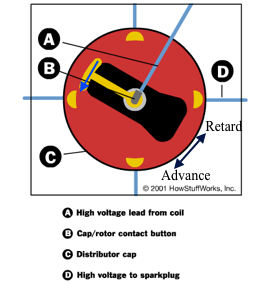
(In more “modern” cars the ignition control is automatic, often controlled by the inlet vacuum or sometimes just mechanical adaptation (by springs and weights) to the engine revs.)

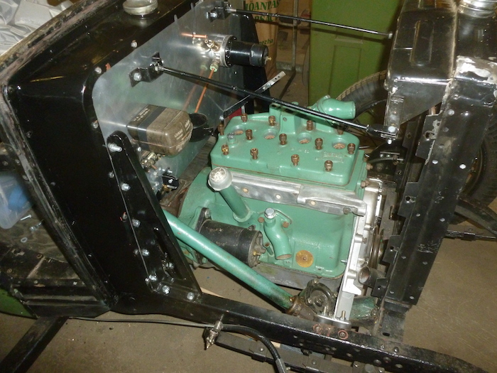
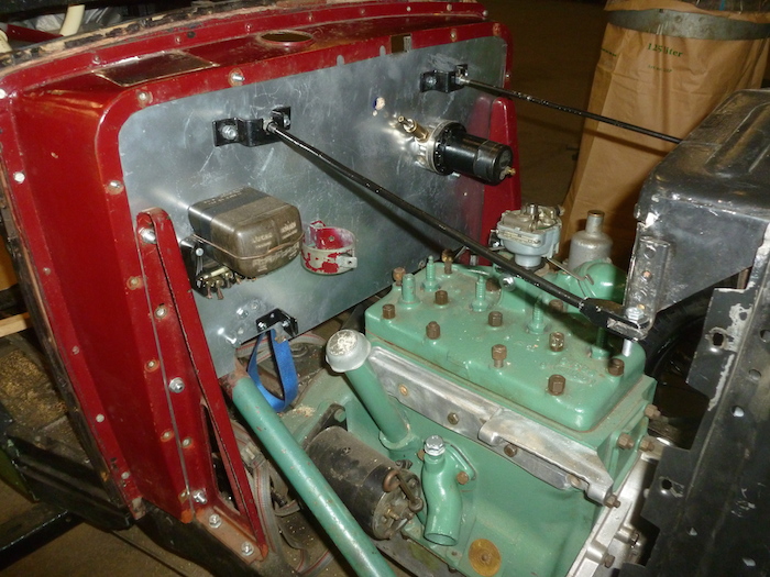
Because the engine moves during acceleration and retardation I needed a mechanical control that ignored these variations. Therefore I chosed  cable control between the drivers control rod and the distributer. This solution needed among some other details design of a couple of brackets to fix the cable ends. And the cable itself must be stiff enough to work in both directions i.e. pull and push the distributor angle.

Tändning 2

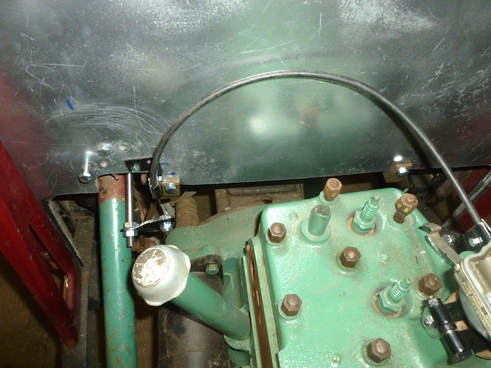
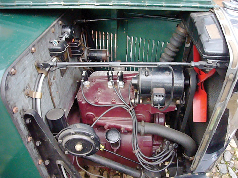
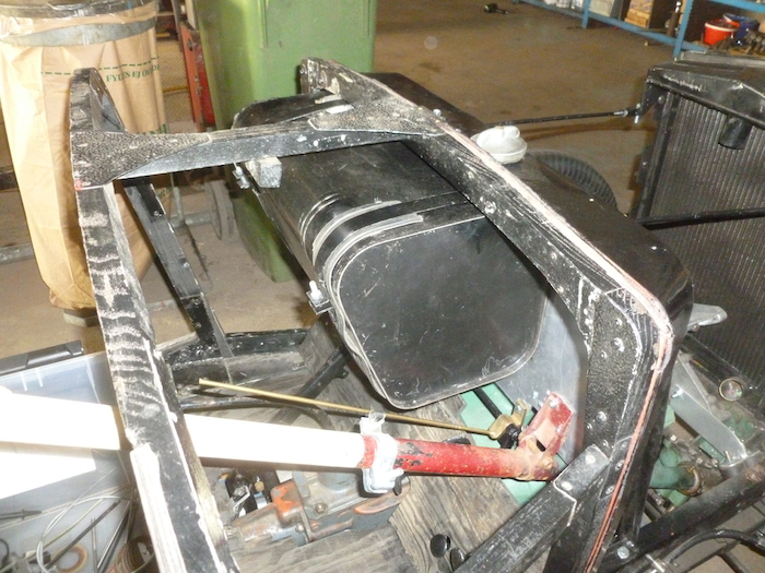
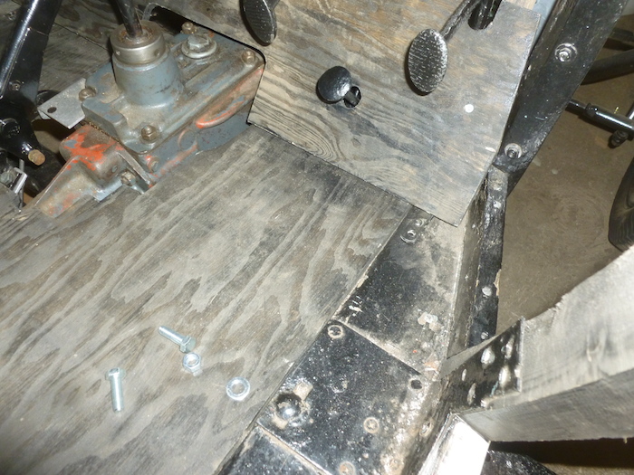
The connection from the drivers control rod and cable.

tändning 1
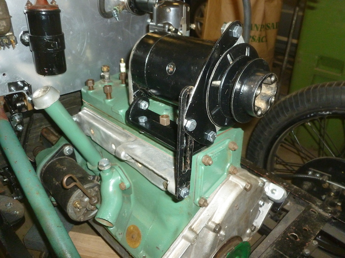
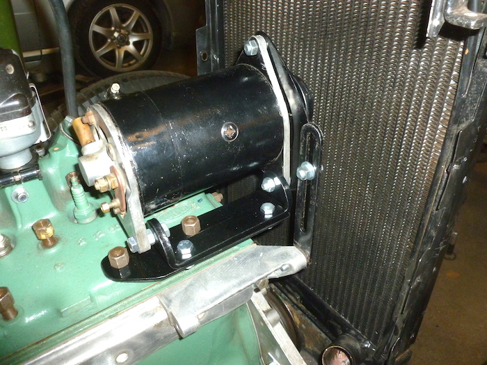
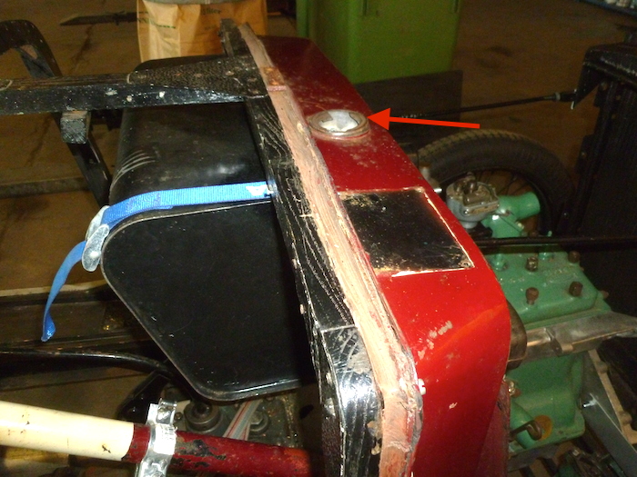
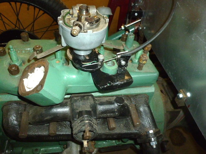
The connection cable to distributor. When the cable push the distributor the ignition is more advanced and vice versa.

It´s then totally up to the driver to “feel and hear” and control the best angle for the distributor consider the speed and force needed at every moment. This is driving for real, isn´t it?

Handbrake, propshaft and the manual ignition control

Handbrake lever is mounted and attached to the brake crossbar. Tested and works well!Handbroms o kardan

The propshaft is also monted and seem to fit as expeted after a slight adjustment of the engine mountings caused by the new and thicker original fabric coupling than the original. There is a slight pressure against the fabric coupling which I suppose is just fine and quite according to the specification.Kardan bakre

The work to design a advance/retard ignition control has started. There seems to exist two different control arrangements. One rather complicated and I’ve seen very high prices on ebay for one of those. The other seems simple enough to make in a ordinary garage. It may not be the correct control for my car but some Minors had them (see the illustration from a Minor manual).Namnlöst

I used a 8 mm bar and a black nob and the rest was not too complicated. Now I need to fix it to the steering column and design how to connect the bar to the distributer… a lot more complicated I´m afraid.Advance retard contol 1